[Update: As featured on Hackaday! :) ]
The Fire TV remote has a neat feature which lets you control other equipment like the TV or a soundbar. The list of manufacturers & devices it’ll control is massive.. but not all encompassing!
I bought an Edifier R1855DB (very similar to the R1850DB), and wanted to control it using the Fire TV remote.. which saves juggling 2 remotes (and the Edifier one is pretty cheap & feels like it could break at any moment!).
I soon found out that this particular Edifier model isn’t in the list of supported devices in the Fire TV equipment control feature which is really frustrating. There’s no route to get added to the Amazon list, nor does it have a ‘learn’ mode.
When I contacted Edifier they said “Our remotes use custom IR codes that can not be inputted into a universal remote”. And “information about the IR code is not open to the public”. Pretty ridiculous.
This is where I got curious about what IR codes the Edifier remote is sending out.. so I took a cheap Arduino Nano microcontroller and an IR receiver & wired them up on a breadboard. There’s an IR library with a bunch of examples, so I used the ‘IR dump’ code, uploaded it to the board & could instantly see the codes from the remote.

Apparently the Edifier R1855DB uses the NEC protocol, which is really common, and you can see the sequences it sends easily enough. I noted down the IR codes for each of the buttons I was interested in, and can now look at transmitting them!
You can get an IR transmitter for the Arduino .. at first I tried an IR LED from an old TV remote, but it needed a transistor to make it work properly, which I didn’t have. So I ended up buying a KY-005 IR module from eBay for £2.50.

Hooking this up to the Arduino was simple, and I tested it was working using more example code from the IR Remote library. Finding the right format to play back the NEC codes I captured was a bit trial-and-error.. I eventually found the raw codes worked best. I actually used a Raspberry Pi with another IR receiver to validate the codes being sent were identical to the original remote.
What I can then do is have an IR receiver AND transmitter hooked up to the same Arduino and have it act as a translator between one manufacturers codes to another.
We can power the Arduino using the USB socket on the TV. This only powers up when the TV is on, which is quite handy.. and if it turns on, we can write some code to send the speaker power on IR command when the Arduino boots.
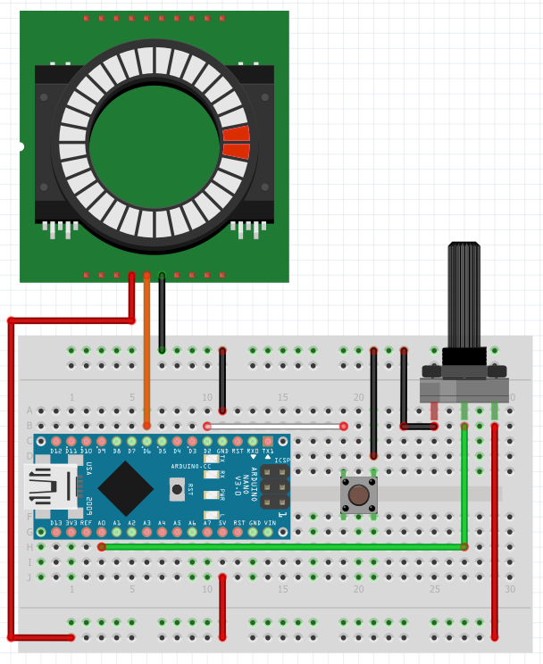
Here’s a quick wiring diagram, showing how everything is connected together;

I didn’t have a cable long enough, so I took an old USB cable, cut it up, and soldered it into the IR transmitter so that I could place it near the Edifier IR receiver.. that was the most fiddly bit of this project.
Once I had that set up, I picked a supported device from the Fire TV equipment list – the Amazon Basics Soundbar – and dumped the IR codes for it from the Fire TV remote.
I then wrote some code to listen for the Amazon Basics Soundbar commands & emit a corresponding Edifier IR code. This worked an absolute treat after a bit of debugging. I even added a sequence detector so you can press Mute x2 then Vol Up to send the speaker power signal in case it somehow gets out of sync. Adapting the code to work with whatever equipment you have should be straightforward..

You can build your own version of this for about £8, and it’s incredibly easy to put together, only requiring some basic electronics and coding skills.
Hope this has been useful.. let me know how you get on if you decide to build one of these yourself.
The GitHub repo for this project has a lot more detail & all the source code you need; https://github.com/mattcuk/IRtranslator
There’s a video of this project on YouTube if you want to see a bit more of the build process and see it working.


You must be logged in to post a comment.